About geometric tolerancing
Geometric dimensioning tolerance or GD&T is a system that elaborates on communicating engineering tolerance. There the language of different symbols used as an engineering drawing. To fill design with life, engineers need an approach or manufacturing mechanism to communicate in the best way. For all such help, geometric dimensioning tolerance is there. There is a particular set of symbols used for defining the relation between multiple features while engineering. One example of tolerances of locations is the true position symbol can communicate more accurately to the designers and engineers.
Symbols and geometric tolerance
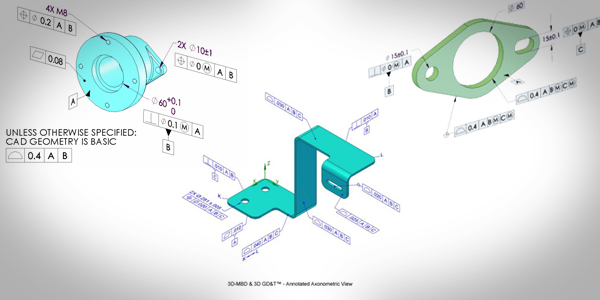
As we all know, geometric dimensioning and tolerancing is based on a symbolic language that enables clear communication between designers and engineers. This standardized symbol language, defined and governed by asme y14.5, helps indicate the allowable deviation of part features from the intended design model. It includes dimensions, tolerances, rules, symbols, and precise definitions that ensure consistency across engineering drawings. Some commonly used symbols and their brief descriptions are listed below:
- True position
The most useful and complex symbol among all is the position symbol. The accurate functioning of the model entirely depends upon the true position symbol used. There are two main methods used for true positioning. However, the positioning relies on the size of the feature.
- Least material condition
Least material as its name shoes is a condition of feature size symbol. It is used for indicating dimensions or size. It describes the least amount of material in particular dimensional tolerance.
- Maximum material condition
The maximum material condition also refers to the feature part’s condition where the maximum material exists under the particular dominion’s tolerance.
- Perpendicularity
Here the symbol of perpendicularity indicates the two multiple things basing on the reference feature which called out. The symbol of perpendicularity controls the 90 degrees perpendicularity of the surface. Mainly the surface perpendicularity controlled using two different parallel plans working n the tolerance zone.
- Datums in GD&T
The symbol of the datum is a plan of an exact theory. The location of the point in the dimensional tolerance area is referenced here. The user can consider it as an anchor for entering. These features are referenced from one another. The datum featured should be controlled while doing measurements.
- Flatness
The most common symbol in the arena of dimensional tolerance is flatness. This symbol references the datum symbol regarding the other features. The flatness symbol becomes more beneficial if the feature defines drawing uniformly. It does so without narrow downing the different dimensions of the drawing.
- Symmetry
Symmetry is the symbol of dimensional tolerance, is related to datum. It applies to maximum material conditions as well as in the least material condition. The symmetry is the three-dimensional tolerance used for ensuring the true feature of the datum plane.
- Runout
Its another symbol is related to the datum. There are no callout drawings. It applies to the least material conditional and maximum material condition. The runout symbol measures the varying reference features from one datum to another when it rotates around 360 degrees. It’s an important symbol to control the condition of circulation.
- Angularity
The angularity symbol expresses the particular orientation of features referenced angle to others. It references a referenced 2D line to another referenced 2D element. More appropriately, it related the orientation of one plane surface to another.
- Straightness
- concentricity
Complex machining benefits
Though the symbols used made it easier to comply with the design and engineering requirements for making a model yet geometrical dimensional tolerance has a significate impact. A complex machine as being an essential part of dimensioning tolerance has a few benefits that listed below:
- uniform and convenient
- saves time and money
- provide accurate communication
- Assist in digital designing
- Ensures dimensional tolerance
Symbols, as well as the features under the dimensional tolerance, assist in saving time and money. Also, it is not so hard to ensure the true position symbol in the drawing.
Conclusion
We found that geometric dimensioning tolerance uses symbols and other features to communicate the designer’s and engineers’ required design from the above conclusion. There are a lot of dimension tolerance symbols used in complex machining for making an accurate model. A true position symbol not only helps in digital designing but also ensures dimensional tolerance. Symbols play a vital role in conveying the exact information.